

How To Repair A Dent In A Pressure Vessel
Identifying Pressure Vessel Nozzle Problems From the Cracking Pattern
Category : Operations
Summary: The following commodity is a part of the National Board Technical Series. This article was originally published in the Summertime 1999 National Board Bulletin.(6 printed pages)
Pressure vessels of "sparse" shell construction that are fabricated from 1/2" thick or less steel plate material are routinely used in the power generation, chemical, petroleum, and nutrient processing industries. Some of these vessels are subjected to relatively severe operating weather that include chemical attack, rapid pressure and temperature fluctuations, and steam/h2o hammer. Every bit a upshot, many owners or operators perform scheduled nondestructive testing of the units to determine a vessel'southward mechanical integrity.
Many of these pressure vessels act as an accumulation bespeak, requiring the units to be equipped with one to 2 dozen nozzles that penetrate the beat and/or heads. These nozzles are often secured to the pressure vessel with fillet welds on both the ID and OD surfaces of the unit of measurement. An acceptable vessel examination procedure includes testing the circumferential welds, the longitudinal welds, and all these nozzle welds.
The most common class of weld nondestructive testing is visual examination, but an increasing number of owners or operators are testing their pressure vessels past the wet fluorescent magnetic particle technique, which is a more than sensitive test procedure. This examination technique can detect surface and slightly subsurface indications in the material. Information technology is not unusual to discover many more indications by wet fluorescent magnetic particle than by visual examination. Yet, because moisture fluorescent magnetic particle examination is not required by the original code construction, the integrity of the code nonetheless remains. A vessel'due south perceived integrity simply becomes questionable after cracking is plant in a vessel that has been examined by the wet fluorescent magnetic particle technique for the start time in its operating life. A more complete resolution of the vessel'south mechanical integrity assessment should be performed by evaluating the indications or cracks found during testing.
Finding indications in the welds and plate material frequently presents the dilemma of what to do adjacent. If the indications are cracks and not plate defects, (such as laps, which compromise the minimum wall thickness of the vessel, or are long and relatively deep) and so the obvious answer is to repair the cracks. Many times, nifty in a weld is interpreted every bit a poor quality weld. To minimize further issues, the old weld is removed and replaced by a new weld.
Regrettably, many cracks are either repaired or new welds are installed without knowing the cause that initiated the cracking in the first place. This lack of noesis can sometimes upshot in further groovy of the same area. Repairing cracks without eliminating the cause of the cracking can be a brusque term solution to a long-term problem. The following three examples demonstrate how the cracking pattern around the smaller nozzles (less than 2") in a force per unit area vessel can assistance identify the source of the problems. These examples are used only every bit an illustration of the evaluation procedure and are not to exist implied as the simply causes resulting in nozzle smashing.
Nifty Due to an External Load
Cracking as the outcome of abnormally high nozzle loads that have exceeded the anticipated or designed nozzle loading is generally characterized by the appearance of "stretch marks" around the weld in the base of operations metal as shown in Figure i. The cracks unremarkably follow the contour of the weld and tear the surrounding base metal due to the weld filler metallic having a college tensile forcefulness than the base metal. Prior weld repairs to the same area signal a persistent problem and are identified by the arrows in Effigy i.
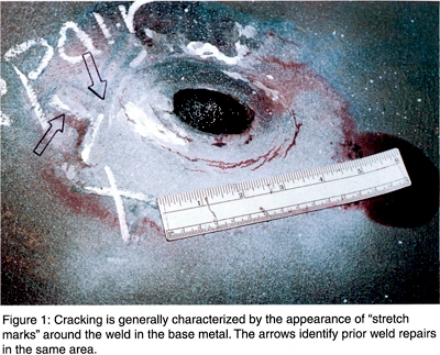
The most common cause of a high external load is the consequence of a poorly designed or a poorly functioning support organisation. This deficiency occurs when the loads are transferred from the support arrangement to the nozzles. These types of loads can result from adding a piece of equipment to the nozzle or connecting pipage without modifying the existing support organization. In addition, loftier loads tin can outcome from a malfunctioning pipe support or added restraint. A visual test of the back up system within the get-go 30 anxiety of the nozzle or pressure vessel will usually identify this sort of problem.
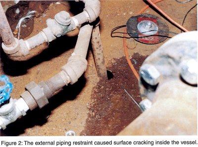
Many vessels are subjected to thermal expansion considering of the temperature increase that occurs nether normal performance. Thermal expansion causes the vessel to increase in size which means the equipment and piping connected to the nozzles must also exist able to move with the vessel. Vessels that are supported and fixed at one cease should accept a sliding back up on the other terminate that enables the vessel to slightly expand and contract. The "stretch mark" blueprint around the nozzle shown in Figure 1 was caused past the add-on of a stock-still restraint to the hi-lo h2o level drain piping. This stock-still restraint was the upshot of the pipe being routed through an undersized hole in the floor plate. Considering the movement of the pipage was restricted by the floor plate, eventually it caused the bleed pipage to bend which resulted in frequent cracking of the nozzle in the ID of the unit equally shown in Figure 2. In other cases that resulted in a similar cleft pattern, restraints had been added to stand up pipes, level transmitters, and chemical feed lines because of either vibration or long pipe connections to the vessel.
Cracking Due to Lack of Penetration
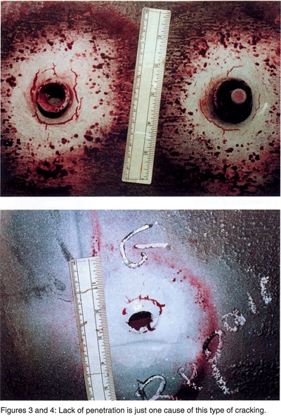
Lack of penetration is the lack of adequate weld filler metal deposit at the root of the joint. The root of a nozzle articulation is the interface between the nozzle wall and the shell or head. This type of cracking volition propagate through the weld in the same pattern as the root, but will intermission the surface of the weld in a radial direction effectually the nozzle if the crack encounters a weld defect such as porosity, slag inclusions, or lack of fusion as shown in Figures 3 and 4. This orientation modify in the cracking can add confusion to the evaluation of the problem. The repair consists of removing all of the fillet weld and preparing the surface area for welding with a pocket-size bore welding rod such equally a iii/32" diameter rod.
Cracking Due to Chemical Attack
Chemical attack of the weld typically occurs in the heat-affected zone (HAZ) in the toe of the weld. The attack occurs at this location because of the slightly dissimilar microstructure created past the welding process. The general appearance of this type of corking is circumferential at the toe of the weld and around most or all of the outer diameter of the weld. The cracking pattern is similar to 1 that can result from fatigue. However, because it is a chemical set on information technology volition occur in nearly all the welds in a item zone of the vessel, such as the locations above or below the liquid level. The cracking pattern from chemical set on is different from fatigue peachy which usually occurs at specific locations that have a recurring or cyclic tensile load applied to the surface area. In the case of chemic attack, a solution would be to repair the weld and make adjustments to the chemical input.
Call up, any long-term repair should remove all signs of the defect and discourage other defects from returning.

Source: https://www.nationalboard.org/Index.aspx?pageID=164&ID=243
Posted by: muellerpory1963.blogspot.com
0 Response to "How To Repair A Dent In A Pressure Vessel"
Post a Comment